

Tag Archives: light
Lens – screen and mirror – what kind of image formed on screen

Pins inside and outside of beaker filled with water – 2012 sciphy practical


A pin in the beaker of water appears higher than its actual position due to refraction of light.
In this experiment, you have to adjust the pin at the cork to a suitable height, such that the pin and the image of the pin inside the beaker of water is aligned and that ‘pins at position of no parallax’ position.
The video below guides you in adjusting the height of the pins to locate correct height.
Similar kind of experiment: Pins with Lens and mirror
Light Experiments – Glass Block and Pins
The video include 3 different light experiments which involve glass block and pins.
Most students faced difficulties in locating the pins through the glass block. It is important to close one eye and use your master eye to view.
Hope this video helps!
In experiments like this, the sources of error include:
– the holes created by the pins are too big, hence the line drawn using the two holes may not be very precise, hence affecting the distance/angle measured (depends on experiments)
– When putting back the glass block back on the paper, the position may be not exactly the same, hence affecting the angle/distance measured.
As a precaution, it is good to ensure that the distance between the two pins are more than 4 – 5 cm. With the holes further apart, the line drawn will be more accurate.
Converging Lens: The 4 Key Scenarios

Ring of Fire Solar Eclipse
View from Bishan-AMK Park, Singapore


Light and sound wave diagram in different mediums with different density
Light and sound are both waves. So both carry energy from one place to another.
Light, which is part of the electromagnetic spectrum, is a transverse wave, It can travel through a vacuum at speed 3.0 x 10⁸ m/s. As the light travels from an optically less dense medium (air) to an optically denser medium (liquid or glass), the light undergoes refraction and bends towards the normal due to a decrease in speed.
Light: Optically less dense medium to denser medium:
– speed decreases
– wavelength shorter
– frequency remains constant
Sound is a longitudinal wave. It requires a medium to pass through and it cannot pass through a vacuum. Opposite to light, as the sound travels from a less dense medium (air) into a denser medium (water or solid), the speed increases.
Sound: Less dense medium to denser medium:
– speed increases
– wavelength longer
– frequency remains constant
Refers to the image below to understand how the waves behave in different mediums.
Click here to revise on the calculation of refractive index for light

Where is the focal point?

Answer: Option A
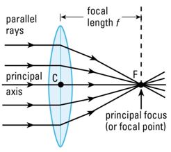
Refer to the diagram (below left) which many are familiar. When parallel rays of light which are parallel to the principal axis enter the lens, the rays bend (refraction), come closer and converge to a point on the principal axis called focal point (F). The distance from the optical centre (C) to the focal point (F) is the focal length (f).
But what if the parallel rays of light entering the lens are not parallel to the principal axis but at an angle as shown on the diagram (below right)?
As you can see, the rays refracted and converge to a point P which is along the focal plane (imaginary vertical line through F and is perpendicular to the principal axis). This is similar to L1 in the question. (Refer to the first section of the video simulation below to reinforce your concept)

How about L2 in the question?
Light is reversible so you can also treat the light rays entering from the right of the lens L2. The parallel rays of light in L2 are at an angle but there is no ray through the optical centre C.
Refer to the video below, as you can see, the parallel rays of light will likewise refract and converge to a point, which is along the focal plane too.
Hence the focal point of both lenses L1 and L2 is at F2. So the answer is Option A.
Finding focal length f of the lens
A thin convex lens is placed on a plane mirror and an object pin is then moved along the axis of the lens until an image is seen to coincide with the object pin when viewed from above. What is then the distance between the pin and the lens? (Take f as the focal length of the lens)
A 0.5 f B 1.0 f C 1.5 f D 2.0 f
Answer: Option B
A common mistake is to assume this is the scenario (2nd scenario) where the object is at 2F and the image formed is at 2F, hence the image is the same size as the object, inverted and real. But this is not the case.
Refer to the video tutorial for the explanation.
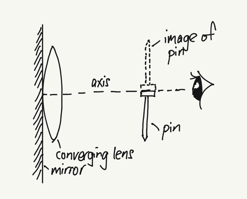
This set up of the lens with the mirror is using the concept that when parallel light rays (parallel to principal axis) enter the lens, the rays will converge to a point after passing through the lens. This point is called the focal point, F. The distance between F and the optical center of lens is the focal length f. Refer to the diagram below.
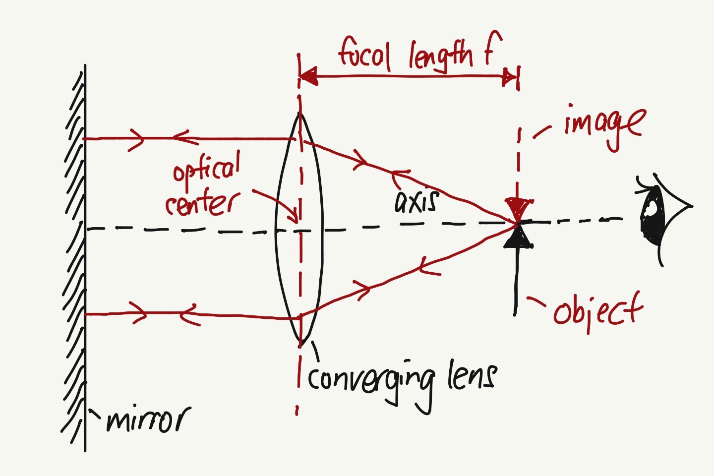
When you adjust the object (pin) until both the object and the image coincide even when you move your eye forward or backward perpendicular to the axis, the distance between the optical center and the object (pin) is the focal length f.
At this position, as the rays from the object pass through the lens, due to refraction, the rays converge and becomes parallel to the axis. Due to the mirror, the parallel rays will be reflected back to the lens and then converge to a point that coincides with the object.
Refer to the video on how to get that position.
Before you start the experiment to find the focal length f, there is a fast and easy way to estimate the f. Refer to the video below.
Below is another image of another set-up but with the same concept.
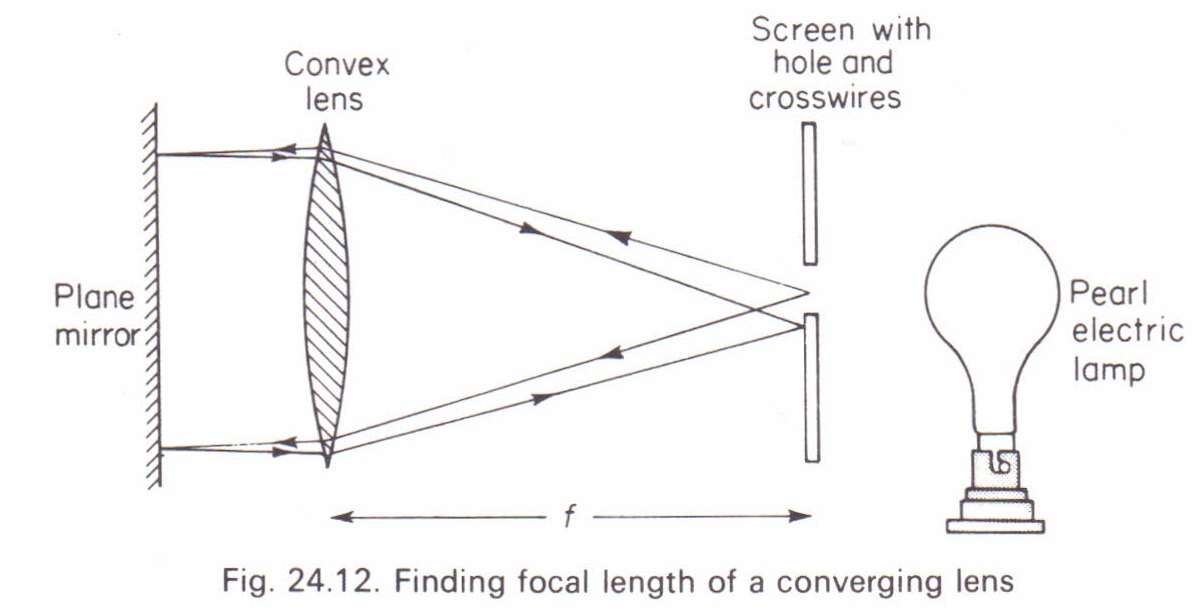
Another similar question below. The answer is Option B
Click here to view the post on a typical lens experiment and things to take note.
Another experiment which involved the same technique. Pins inside and outside the beaker of water
Identifying what lens, focal length and image from 2 rays – PP2010P1Q23 and SP2014P1Q11
These 2 questions are actually the same. Q23 is from 2010 Pure Physics P1 while Q11 is from 2014 Sci Physics P1. Take a look at these 2 questions. If you are not sure, view the video below for the explanation.

Answer to Q23: Option A

Answer to Q11: Option D
If you do not know how to answer these 2 questions, view this video and also refer to the lens summary below.

Different Lens Ray Diagram questions
Drawing ray diagrams for converging lens come in many forms. But the basic concepts needed are the 3 rays (which have rules to follow) to locate the image. The following ray diagrams for the 4 scenarios must be learned well, together with the respective image characteristics and applications.
With the basic concepts learned, when questions are asked in different ways, you should be able to draw the ray diagrams. Refer to some different ray diagram questions below and their video tutorials.


Click the followings for other lens ray diagram questions. https://evantoh23.wordpress.com/2010/11/09/20101109converging-lens-important-concepts/
https://evantoh23.wordpress.com/2015/08/27/olevel-sp-p1-focal-length-of-lens-using-distant-object/
3 possibilities when light ray travels from an optically denser medium towards an optically less dense medium

Refer to the example below.

