
These are some of the necessary electrical symbols that you must know. Those in grey background are for Pure Physics.
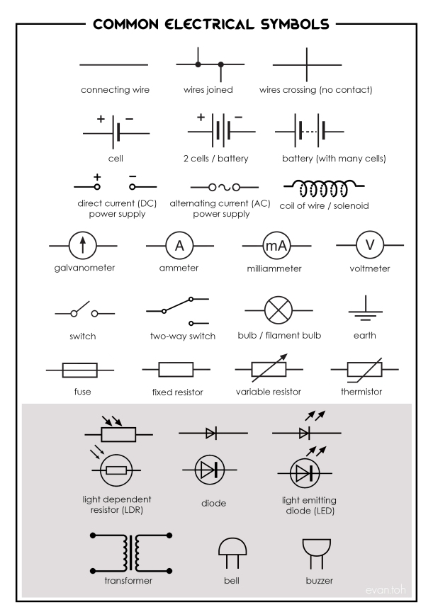

These are some of the necessary electrical symbols that you must know. Those in grey background are for Pure Physics.
This impressive Bugatti Chiron can accelerate from rest to 400 km/h and decelerate to a complete stop in merely 42 seconds! Our normal cars on the expressway travel about 90 km/h and the F1 race yesterday night is about 300 km/h. This Bugatti Chiron is faster than most bullet trains and comparable to the speed of a magnetic levitation train!
 https://www.bugatti.com/chiron
Before we look at the video, let’s do some calculations:

Let’s find the acceleration of the car to reach 400 km/h in 32.6 sec:
Converting 400 km/h to m/s: 400km/1h = 400 000m/3600s =111 m/s
acceleration, a = (v – u)/t = (111 – 0) / 32.6 = 3.4 m/s2
hmmm…. this acceleration doesn’t seem impressive… it is way below free fall acceleration!
But we are not being fair here. To achieve the max speed of 400 km/h is not easy due to the resistive force (air resistance and friction) as speed increases. We should compare fairly the acceleration to reach 100 km/h instead like how we typically compare sports car like Ferrari etc.
Let’s find the acceleration of the car to reach 100 km/h (27.8 m/s) in 2.4 sec:
acceleration, a = (v – u)/t = (27.8 – 0) / 2.4 = 11.6 m/s2
This is greater than acceleration due to gravity (free fall) and much faster than most sports cars in the market like Ferrari or Lamborghini!
Now, let’s find the deceleration of the car when it slows down from 400 km/h to a complete stop in 41.9 – 32.6 = 9.36 s
acceleration, a = (v – u)/t = (0 – 111) / 9.36 = -11.9 m/s2
Take note of the spoiler being activated when it decelerates. This increases the drag (air resistance) to slow down the car, in addition to using the normal brakes. It is the same principle as the aeroplane when it lands and slows down on the runway.
Interesting musical instrument – theremin
These 2 questions are actually the same. Q23 is from 2010 Pure Physics P1 while Q11 is from 2014 Sci Physics P1. Take a look at these 2 questions. If you are not sure, view the video below for the explanation.

Answer to Q23: Option A

Answer to Q11: Option D
If you do not know how to answer these 2 questions, view this video and also refer to the lens summary below.

To find the unknown resistor R, the following apparatus are setup.

Refer to the video below for the setting up of the apparatus.
Why do you need a variable resistor (rheostat)?


For pure metallic conductor, like the fixed resistor R, it obeys the Ohm’s Law, hence it is an ohmic conductor.
From the graph, the current I flowing the conductor is directly proportional to potential difference V across the conductor, provided physical conditions like temperature remains constant. [the graph is a straight line with constant gradient, and passes through the origin]


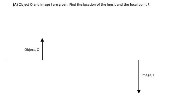
Drawing ray diagrams for converging lens come in many forms. But the basic concepts needed are the 3 rays (which have rules to follow) to locate the image. The following ray diagrams for the 4 scenarios must be learned well, together with the respective image characteristics and applications.
With the basic concepts learned, when questions are asked in different ways, you should be able to draw the ray diagrams. Refer to some different ray diagram questions below and their video tutorials.


Click the followings for other lens ray diagram questions. https://evantoh23.wordpress.com/2010/11/09/20101109converging-lens-important-concepts/
https://evantoh23.wordpress.com/2015/08/27/olevel-sp-p1-focal-length-of-lens-using-distant-object/
For Combined Science Physics Olevel, when constructing vector diagram, a method called Parallelogram Method is commonly used.
Parallelogram Method is used when 2 forces are known, and the resultant (net) force R, can be found.
Below show 5 different variations of questions when can be solved by using Parallelogram Method:
(A) Body has acceleration, forces are unbalanced, there is a resultant force R (Newton’s 2nd law)
(B) Body at rest, all forces are balanced, there is no resultant force R (Newton’s 1st law)
(C) Body moving at constant velocity, all forces are balanced, there is no resultant force (Newton’s 1st law)
(D) Finding unknown force (with resultant force R + another known force are given)
(F) Vector diagram is applicable to all vector quantities (with magnitude and direction). Not just for forces.
Click here to view video tutorials on how to construct parallelogram step-by-step


For Pure Physics, another method is the closed-loop triangle, where only 1 known force with 2 other unknown force. Click here to view the video tutorials.


Electric field

Electric field line

Electric field direction
Click here to understand more about electric field, field line and field direction.

Click here to understand more about inertia.

Solutions: Option B
You can view the video tutorial here or the written solutions below.


Solutions: Option D
You can view the video tutorial here or the written solutions below.
(You can click here to view another post on similar question where angle is given instead)


Solutions: C
Alternatively, you may put values to work out using the 2 basic formulae of P = IV and V = IR. Refer the video below.


