To do similar questions, it is important to know the 3 rays which have rules to follow in order to locate the image. Look through the video to learn the concepts and hopefully you can do similar questions in future.


To do similar questions, it is important to know the 3 rays which have rules to follow in order to locate the image. Look through the video to learn the concepts and hopefully you can do similar questions in future.


Click on the link below to view another similar question.


Answer: B

Light summary in progress 🙂


A pin in the beaker of water appears higher than its actual position due to refraction of light.
In this experiment, you have to adjust the pin at the cork to a suitable height, such that the pin and the image of the pin inside the beaker of water is aligned and that ‘pins at position of no parallax’ position.
The video below guides you in adjusting the height of the pins to locate correct height.
Similar kind of experiment: Pins with Lens and mirror
The video include 3 different light experiments which involve glass block and pins.
Most students faced difficulties in locating the pins through the glass block. It is important to close one eye and use your master eye to view.
Hope this video helps!
In experiments like this, the sources of error include:
– the holes created by the pins are too big, hence the line drawn using the two holes may not be very precise, hence affecting the distance/angle measured (depends on experiments)
– When putting back the glass block back on the paper, the position may be not exactly the same, hence affecting the angle/distance measured.
As a precaution, it is good to ensure that the distance between the two pins are more than 4 – 5 cm. With the holes further apart, the line drawn will be more accurate.


The video below shows a typical lens experiment. (reference to O-Level SciPhy 2015). I will briefly go through the set-up, main steps and how to get the 1st set of readings.
In the next video, it highlights the various types of lens practical which you might have in the school lab. e.g. different kind of crossed-wire, a beaker of water as a converging lens and different kind of images formed.
Key points:
1) Make sure the object (illuminated crossed-wire), lens and screen are aligned properly.
2) Source of Error: identifying the sharpest image
Improvement: (i) Repeat the experiment a few times for the same
independent variable to identify the sharpest image.
(ii) Move the lens (or screen) forward and backward about
the sharp image, until the sharpest image is determined.
3) In general, the focal lens of the lens used in the lab is usually 10 cm or 15 cm. Most lens experiment requires you to find the focal length. There is also a easy way to quickly determine the focal length before starting the experiment.
Refer to this post for another lens experiment which is different and more challenging.
View from Bishan-AMK Park, Singapore


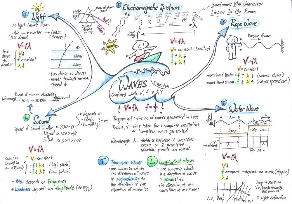
Light and sound are both waves. So both carry energy from one place to another.
Light, which is part of the electromagnetic spectrum, is a transverse wave, It can travel through a vacuum at speed 3.0 x 10⁸ m/s. As the light travels from an optically less dense medium (air) to an optically denser medium (liquid or glass), the light undergoes refraction and bends towards the normal due to a decrease in speed.
Light: Optically less dense medium to denser medium:
– speed decreases
– wavelength shorter
– frequency remains constant
Sound is a longitudinal wave. It requires a medium to pass through and it cannot pass through a vacuum. Opposite to light, as the sound travels from a less dense medium (air) into a denser medium (water or solid), the speed increases.
Sound: Less dense medium to denser medium:
– speed increases
– wavelength longer
– frequency remains constant
Refers to the image below to understand how the waves behave in different mediums.
Click here to revise on the calculation of refractive index for light

Though slinky coil is commonly used to demonstrate transverse and longitudinal waves, you must not quote it as an example for either of the waves.
Transverse Waves (slinky coil)
Longitudinal Waves (slinky coil)
Transverse Waves Animation
Longitudinal Waves Animation
Click here to see the simulations of transverse and longitudinal waves.
1. Converging lens (convex lens)
Converging lens, also known as convex lens, is thicker at the centre. Below shows some examples.

In O-level, we learned about symmetrical converging lens. i.e. the curvature of the lens are the same on both sides. As light rays pass through the converging lens, the rays come closer together.

Take note that the bending of light, refraction, takes place on the air-glass boundaries on both sides of the lens (as shown above). But for easy drawing, we draw the bending at the imaginary centre vertical which passes through the optical centre as shown below.

2. The 3 Rays
The following 3 rays are important for us to construct the ray diagram and locate the image. We always draw these 3 rays as they have rules to follow, hence guiding us in our drawing.
 Refer to the video below for better understanding of the 3 rays.
3. The 4 Key Scenarios
Depending on the distance of the object to the centre of the lens (object distance u), the kind of image you get varies.

Refer to the video below for the better understanding of how the various images are formed.
3. The Pattern
Besides knowing the 4 key scenarios, it is important to know how the image behaves as the object is moved towards the lens.
In general, as the object (starting from a distance of >2f) moves closer to the lens, the image will move further away from the lens and the size of the image becomes bigger.
But when the object is within a focal length, as it moves closer to the lens, the virtual image moves closer to the lens and it becomes smaller compared to the image previously. But the virtual image is always bigger than the object.
Refer to the video for better visualisation and understanding.
4) Other posts on converting lens:
What is focal length and how to identify
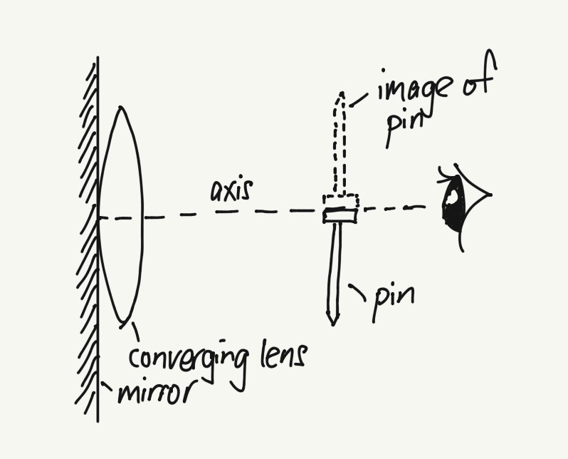
Finding focal length f of the lens (using a mirror and pin practical experiment)
Different converging lens ray diagram questions (must know)
Different ways to have a sharp image formed on the screen
Which distance is the focal lens of the converging lens? Olevel question

Answer: Option A
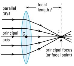
Refer to the diagram (below left) which many are familiar. When parallel rays of light which are parallel to the principal axis enter the lens, the rays bend (refraction), come closer and converge to a point on the principal axis called focal point (F). The distance from the optical centre (C) to the focal point (F) is the focal length (f).
But what if the parallel rays of light entering the lens are not parallel to the principal axis but at an angle as shown on the diagram (below right)?
As you can see, the rays refracted and converge to a point P which is along the focal plane (imaginary vertical line through F and is perpendicular to the principal axis). This is similar to L1 in the question. (Refer to the first section of the video simulation below to reinforce your concept)

How about L2 in the question?
Light is reversible so you can also treat the light rays entering from the right of the lens L2. The parallel rays of light in L2 are at an angle but there is no ray through the optical centre C.
Refer to the video below, as you can see, the parallel rays of light will likewise refract and converge to a point, which is along the focal plane too.
Hence the focal point of both lenses L1 and L2 is at F2. So the answer is Option A.
A thin convex lens is placed on a plane mirror and an object pin is then moved along the axis of the lens until an image is seen to coincide with the object pin when viewed from above. What is then the distance between the pin and the lens? (Take f as the focal length of the lens)
A 0.5 f B 1.0 f C 1.5 f D 2.0 f
Answer: Option B
A common mistake is to assume this is the scenario (2nd scenario) where the object is at 2F and the image formed is at 2F, hence the image is the same size as the object, inverted and real. But this is not the case.
Refer to the video tutorial for the explanation.
This set up of the lens with the mirror is using the concept that when parallel light rays (parallel to principal axis) enter the lens, the rays will converge to a point after passing through the lens. This point is called the focal point, F. The distance between F and the optical center of lens is the focal length f. Refer to the diagram below.
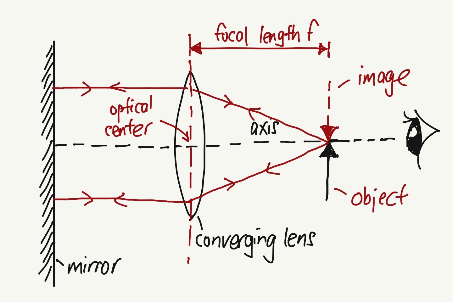
When you adjust the object (pin) until both the object and the image coincide even when you move your eye forward or backward perpendicular to the axis, the distance between the optical center and the object (pin) is the focal length f.
At this position, as the rays from the object pass through the lens, due to refraction, the rays converge and becomes parallel to the axis. Due to the mirror, the parallel rays will be reflected back to the lens and then converge to a point that coincides with the object.
Refer to the video on how to get that position.
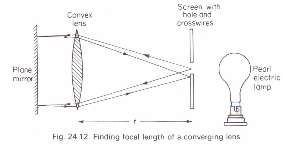
Before you start the experiment to find the focal length f, there is a fast and easy way to estimate the f. Refer to the video below.
Below is another image of another set-up but with the same concept.
Another similar question below. The answer is Option B
Click here to view the post on a typical lens experiment and things to take note.
Another experiment which involved the same technique. Pins inside and outside the beaker of water

Another great company!
Using refraction and reflection of sunlight to provide lighting in building!
These 2 questions are actually the same. Q23 is from 2010 Pure Physics P1 while Q11 is from 2014 Sci Physics P1. Take a look at these 2 questions. If you are not sure, view the video below for the explanation.

Answer to Q23: Option A

Answer to Q11: Option D
If you do not know how to answer these 2 questions, view this video and also refer to the lens summary below.
Drawing ray diagrams for converging lens come in many forms. But the basic concepts needed are the 3 rays (which have rules to follow) to locate the image. The following ray diagrams for the 4 scenarios must be learned well, together with the respective image characteristics and applications.
With the basic concepts learned, when questions are asked in different ways, you should be able to draw the ray diagrams. Refer to some different ray diagram questions below and their video tutorials.


Click the followings for other lens ray diagram questions. https://evantoh23.wordpress.com/2010/11/09/20101109converging-lens-important-concepts/
https://evantoh23.wordpress.com/2015/08/27/olevel-sp-p1-focal-length-of-lens-using-distant-object/

Refer to the example below.

‘Li-fi 100 times faster than wi-fi’

Solutions: Option D
Reflection of light using a mirror
Refraction of light using various shaped optical mediums
Total Internal Reflection (TIR) using a semi-circular perspex
For Total Internal Reflection (TIR) to occur:
1) angle of incidence i is greater than the critical angle c
2) the light is travelling from an optically denser medium towards a less dense medium
Which distance is equal to the focal length of a lens?
(A) the distance between a distant object and the image
(B) the distance between the image of a close object and the centre of the lens
(C) the distance between the image of a distant object and the centre of the lens
(D) the distance between two principal foci
Solutions: Option C
Focal length f is the distance between the focal point and the centre of the lens (optical centre).
Note that only when parallel rays of light enter a converging lens, the rays will converge to a point. That point is considered to be focal point F (principal focus). The distance between focal point F and the optical centre is the focal length f. Refer to below.
As none of the options is similar to the above definition, you have to consider that the rays from a distant (far away) object are considered parallel. Hence the sharp image formed on the screen is considered the forcal point F of the lens and the distance between the image and the optical centre is the focal length f.

If it is a close object, the rays entering are not considered parallel. Hence even if the rays converged to a point, that point is NOT focal point F and the distance between this converged point and the optical centre is NOT focal length f.

Click the following posts for other lens concepts:
https://evantoh23.wordpress.com/2017/08/19/different-lens-ray-diagram-questions/
https://evantoh23.wordpress.com/2010/11/09/20101109converging-lens-important-concepts/
Overview of Total Internal Reflection (TIR)

Explanation of the various stages:

Solutions:
a) 38.8o b) 41.8o
c) 51.2o . The ray does not emerge as total internal reflection has occurred. The angle of incidence is greater than critical angle and the light is traveling from a denser towards a less dense medium.
Click here to view the video tutorial for working and explanation for (a) and (b).
Click here to view the video tutorial for working and explanation for (c) and (d).

Solutions:
a) Refraction b) 48.6o c) c = 41.8o e) 70o
d) Total internal reflection has occured, as the angle of incidence is greater than critical angle and the light is traveling from a denser medium (glass) towards a less dense medium (air)
Click on the video tutorial for explanation and working for part (a) and (b).
Click on the video tutorial for explanation and working for part (c) to (e).

Refer to this link to learn the basic concepts of Total Internal Reflection
For total internal reflection (TIR) to occur,
1) angle of incidence (i) > critical angle (c)
2) light is traveling from a denser medium towards a less dense medium
Important concepts:
1) angle of incidence is the angle between the incident ray and normal
2) when the angle of incidence i = 0, light will pass through without bending


Refer to the following post on the physics concepts involved.

Solutions: Option C

Solutions: Option C


Answer is A.
Many thought it is a diverging lens due to the ray which seems to diverge out. If you refer to the sketch esp the highlighted ray in pink, you will realise that it is converging lens.
Likewise you will be able to see that object is less than focal length in order to have such ray.


Optical fibre network technology allows us to surf net approximately 100 times faster than our current Internet connections.
Optical fiber cables are thin strands of glass, about the thickness of a human hair, that permit the transmission of data using light over longer distances and at higher connection speed of 1Gbps and above. The blue and red cables in the photo are the optical fibre cables.
The transmission of light through the optical fibre cable uses physics concept of Total Internal Reflection (TIR).
For TIR to occur,
1) light must be traveling from a denser to less dense medium.
2) incidence angle is greater than critical angle.
The diagram shows four lamps in front of a plane mirror. The card prevents the observer at X from seeing the lamps directly, although the image of one lamp can be seen in the mirror.
Which lamp’s image can be seen?
Solution: B


